
|
|
| Configure > Registers | Previous | Next |
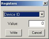
The "Registers" is mainly for information purposes and is rarely necessary to be altered by the user. Register definitions are provided below. The first five options can be changed in Setupand should not be altered here. The rest are provided for your information. The comments on the right are headings for the addresses and definitions listed on the left. These use the ModBus protocol.
----------------------------------------------------------
Register definition
addr def Comment
0000 int16 Device ID 0 For DI-1000TC-4, 1 for DI-1000TC-8
0002 int16 Device address 1 to 127 supported
0004 int16 Chain Address First address for chaining
0006 int16 Master Master address; send buffer next
0008 int16 Baudrate 0 - 5: 4.8, 9.6, 19.2, 38.4, 57.6, 115.2 kbaud
0010 signed int16 offset channel 1 Offset calibration
0012 signed int16 offset channel 2
0014 signed int16 offset channel 3
0016 signed int16 offset channel 4
0018 signed int16 offset channel 5
0020 signed int16 offset channel 6
0022 signed int16 offset channel 7
0024 signed int16 offset channel 8
0026 signed int16 offset CJC
0028 int16 scale channel 1 Scale calibration
0030 int16 scale channel 2
0032 int16 scale channel 3
0034 int16 scale channel 4
0036 int16 scale channel 5
0038 int16 scale channel 6
0040 int16 scale channel 7
0042 int16 scale channel 8
0044 int16 scale CJC
0046 int16 chan_list0 Channel scan list 0 - 8(8 = cjc)
0048 int16 chan_list1
0050 int16 chan_list2
0052 int16 chan_list3
0054 int16 chan_list4
0056 int16 chan_list5
0058 int16 chan_list6
0060 int16 chan_list7
0062 int16 chan_list8
0064 int16 scanrate divisor
0066 int16 max buffer Buffer can be from 1 to 36 positions
// this marks the end of the power up locations
0068 60 reserved locations
0128 int16 TC_type_list0 Thermocouple type list 0 - 7 J, K, T, R, S, B, E
0130 int16 TC_type_list1
0132 int16 TC_type_list2
0134 int16 TC_type_list3
0136 int16 TC_type_list4
0138 int16 TC_type_list5
0140 int16 TC_type_list6
0142 int16 TC_type_list7
0144 int16 TC_type_list8
0146 char[62] User annotation null terminated ascii string
/*
These ram locations are initialized from eeprom.
They are addressed with an offset of 0x4000
*/
int16 ID; //device ID 0 for DI-1000TC-1 1 for DI-1000TC-2
int16 slvaddr; //device's slave address
int16 chainaddr; //auto scan slave addr
int16 clkfreq; //device base clock freq. in kilohertz
int16 baudrate; //baud rate
signed int16 offset[9]; //channel calibration offset
int16 scale[9]; //channel calibration scale
int16 scan_list[9]; //device scan list
int16 scanrate; //scan rate devisor
int16 maxbufptr; //max buffer position should be <=36
// end of power up locations
int16 command; //command
/*
bit data description
0 0 or 1 Power 0 = off(default); 1 = on
1 0 or 1 Scan 0 = off(default); 1 = on
2 0 or 1 Pacer Clock 0 = Internal(default); 1 = external
3 0 or 1 Master Clock 0 = off(default); 1 = on
4 0 or 1 Auto Scan Mode 0 = off; 1 = on
5 0 or 1 Master for Auto Scan Mode 0 = slave(default); 1 = master
6 reserved
7 reserved
8 reserved
9 reserved
10 reserved
11 reserved
12 reserved
13 reserved
14 0 or 1 Or data with command data bits 0 thru 13
15 0 or 1 And data with command data bits 0 thru 13
*/
int16 bufptr; //buffer pointer
int16 scan_rate_cntr; //isr counter
/*
The buffer is addressed with an offset of 0x5000
*/
signed int16 databuf[36]; //averaged data